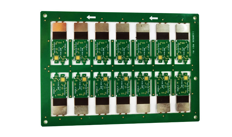
Do you know Rigid Flex PCB Design considerations? What's the differences between between Rigid PCB Design and Flex PCB Design? Today let us Rigid Flex PCB Manufacturer tell you.
Most of the design elements of rigid PCB have been applied to the design of flexible PCB. However, there are other new elements that need attention.
Metal Stiffener Rigid-Flex PCB
1. Current carrying capacity of the wire
Because flex PCB have poor heat dissipation (compared to rigid PCB), sufficient wire width must be provided. When some wires carrying large currents are placed face to face or adjacent to each other, additional wire width or spacing must be given in consideration of the problem of heat concentration.
2. Shape
Wherever possible, rectangles should be preferred wherever possible, as this would result in better substrate savings. There should be enough free margins near the edges, depending on the possible remaining space of the substrate.
In shape, the inner corner should appear to be circular; the pointed inner corner may cause tearing of the panel.
Smaller wire widths and spacing should be minimized as much as possible. If the geometric space allows, the thin wires that are closely packed should become wide wires. The wires that terminate at the plated through holes or component mounting holes should be smoothly searched into the pads. As a general standard, any change from straight line to image angle or different line width must be as smooth as possible. Sharp corners will naturally concentrate stress and cause wire failure.
3. Flexibility
As a general standard, the bend radius should be designed to be as large as possible. The use of thinner laminates (for example: 50μm copper foil instead of 125μm copper foil) and wider conductors can better increase the likelihood of more cyclic bending. Single-sided flexible PCB typically show better performance for a large number of bending cycles.
4. Pad
Around the pad, there is a change from a flexible material to a rigid material. This area is more likely to break the conductor. Therefore, the pads should be avoided in areas where bending is likely to occur. The general shape of the pad should be like a teardrop, and the film must cover the seam of the pad.
5. Rigid reinforcement board
In the mass production of small electronic devices such as small calculators, flexible PCB incorporating a rigid laminated laminate reinforcement plate have become very popular and are also more cost effective. The flexible PCB is mounted on a rigid board (such as grade G-10) with suitable slots for future separation. After component assembly and wave soldering, the rigid plate is divided into different sections by cutting to facilitate folding into the desired shape.

没有评论:
发表评论