2020年3月27日星期五

Several Classifications of Flexible Printed Circuit Boards

Today Flexible Board Manufacturer will give you a brief description of several categories of flexible printed circuit boards.

At present, there are four types of flexible circuits: single-sided, double-sided, multilayer, and rigid-flex circuit boards.

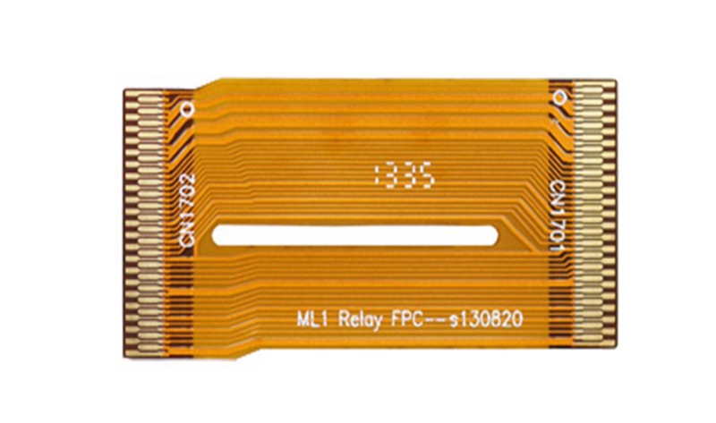
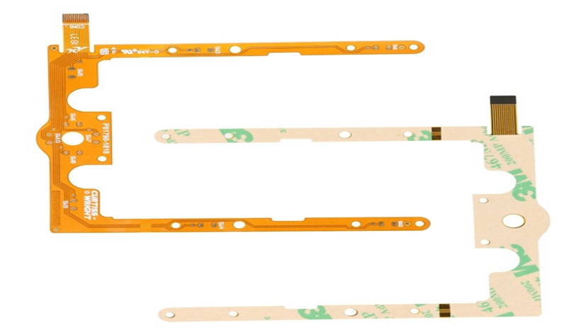
① The single-sided flexible board is the printed board with the lowest cost and low electrical performance requirements. For single-sided wiring, single-sided flexible boards should be used. It has a layer of chemically etched conductive pattern, and the conductive pattern layer on the surface of the flexible insulating substrate is a rolled copper foil. The insulating substrate may be polyimide, polyethylene terephthalate, aramid fiber ester, and polyvinyl chloride.

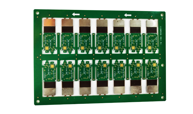
② Double Sided Flexibl PCB is a conductive pattern made by etching one layer on each side of the insulating base film. The metallization holes connect the two sides of the insulating material to form a conductive path to meet the design and use functions of flexibility. The cover film protects single and double-sided wires and indicates where the component is placed.
Double Sided Flexibl PCB

③ Multi-layer flexible board is a single-sided or double-sided flexible circuit with 3 or more layers laminated together, forming metallized holes by drilling collar L, electroplating, and forming conductive paths between different layers. This eliminates the need for complicated welding processes. Multilayer circuits have huge functional differences in terms of higher reliability, better thermal conductivity, and easier assembly performance. When designing the layout, the interaction of assembly size, number of layers and flexibility should be considered.

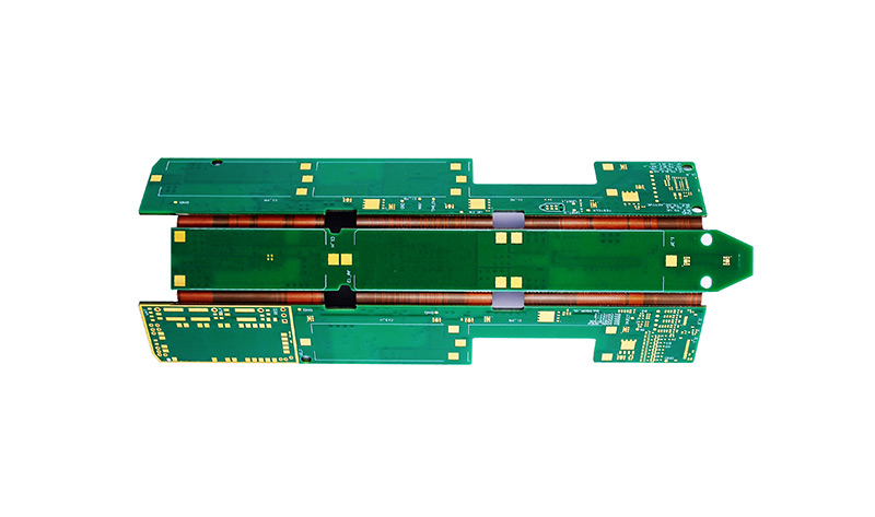
④ The traditional Rigid Flex PCB is composed of rigid and flexible substrates selectively laminated together. The structure is compact. If a printed board has components on its front and back, a rigid-flex board is a good choice. However, if all the components are on one side, it is more economical to use a double-sided flexible board and laminate a layer of FR4 reinforcement on the back.

The flexible circuit of the hybrid structure is a multilayer board, and the conductive layer is composed of different metals. An 8-layer board uses FR-4 as the inner layer of the medium and polyimide as the outer layer of the medium. The leads extend from the motherboard in three different directions, and each lead is made of different metals. Constantan alloy, copper and gold are used as independent leads. This kind of hybrid structure is mostly used in the relationship between electrical signal conversion and heat conversion, and the electrical performance is relatively harsh, and it is the only feasible solution. It can be evaluated by the convenience of the interconnect design and the total cost to achieve the best performance-price ratio.
2020年3月22日星期日

Surface Treatment Process of PCB Circuit Board

The environmental issues involved in the current PCB production process are particularly prominent. Current topics on lead and bromine are the hottest; lead-free and halogen-free will affect PCB development in many ways. Although at present, the changes in the surface treatment process of PCBs are not very large and seem to be relatively distant, but it should be noted that long-term slow changes will lead to huge changes. With the growing demand for environmental protection, the surface treatment process of PCBs will definitely change dramatically in the future.

The purpose of surface treatment The most basic purpose of surface treatment is to ensure good solderability or electrical properties. Since copper in nature tends to exist in the form of oxides in the air, it is unlikely to remain as copper for a long time, so other treatments of copper are needed. Although most of the copper oxides can be removed with a strong flux in subsequent assembly, the strong flux itself is not easy to remove, so the industry generally does not use strong flux.

Flexible PCB
Flexible PCB

The five common surface treatment processes now have many PCB surface treatment processes. The five common processes are hot air leveling, organic coating, chemical nickel plating / gold immersion, silver immersion and tin immersion. The following Multilayer Flexible PCB Manufacturer will One by one for everyone.

1. Hot air leveling Hot air leveling, also known as hot air solder leveling, is a process of coating molten tin-lead solder on the PCB surface and leveling (blowing) with heated compressed air to form a layer that is resistant to copper oxidation and can Provides a good solderability coating. heat

2. Organic coating The organic coating process is different from other surface treatment processes in that it acts as a barrier layer between copper and air; the organic coating process is simple and low cost, which makes it widely used in the industry.

3. Electroless nickel plating / gold immersion The chemical nickel plating / gold immersion process is not as simple as organic coating, the chemical nickel plating / gold immersion seems to put a thick armor on the PCB; in addition, the chemical nickel plating / gold immersion process is not like Organic coating serves as a rust-proof barrier layer, which can be useful and achieve good electrical properties during long-term use of the PCB. Therefore, electroless nickel plating / immersion gold is a thick, good electrical nickel-gold alloy wrapped on the copper surface, which can protect the PCB Board for a long time.

4. The silver immersion silver immersion process is between organic coating and chemical nickel plating / immersion gold, the process is relatively simple and fast; it is not as complicated as chemical nickel plating / immersion gold, nor is it a thick layer of PCB Armor, but it still provides good electrical performance.

5. Immersion tin Since all solders are currently tin-based, the tin layer can match any type of solder. From this point of view, the immersion tin process has great development prospects.

6. Other surface treatment processes There are few applications of other surface treatment processes. Let ’s look at the relatively more applied nickel-gold plating and electroless palladium plating processes. Electroplated nickel gold is the originator of PCB surface treatment technology. It has appeared since the emergence of PCB, and it has gradually evolved into other methods. It is coated with a layer of nickel and then a layer of gold on the PCB surface conductor. Nickel plating is mainly to prevent the diffusion between gold and copper.

The above is the surface treatment process of PCB circuit board introduced by Flexible PCB Factory.

2020年3月16日星期一

What is a Multilayer Circuit Board?

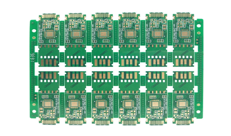
Multi-layer circuit boards, as the name suggests, can be called a multi-layer circuit board with more than two layers, such as 4 Layers PCB, six layers, eight layers, and so on. Of course, some designs are three-layer or five-layer circuits, also called multilayer PCB board. Larger than the two-layer board, there is an insulating substrate between the layers. After each layer of the printed circuit is printed, it is laminated to overlap each layer of circuits. After that, a hole is drilled, and a via is used to achieve conduction between each layer of lines. The advantage of multi-layer PCB circuit board is that the circuit can be distributed in multiple layers for wiring, so that more precise products can be designed. Or smaller products can be achieved through multilayer boards. Such as: mobile phone circuit boards, miniature projectors, voice recorders and other relatively bulky products. In addition, multiple layers can increase design flexibility, better control of differential impedance and single-ended impedance, and better output of some signal frequencies.

Multilayer PCB Board

Multilayer PCB Board

Multilayer PCB Board is an inevitable product of the development of electronic technology towards high speed, multi-function, large capacity and small volume. With the continuous development of electronic technology, especially the extensive and in-depth application of large-scale and ultra-large-scale integrated circuits, multilayer printed circuits are rapidly developing towards high density, high precision, and high-level digitalization. , Blind hole buried hole high plate thickness aperture ratio and other technologies to meet the needs of the market. Due to the computer and aerospace industry's need for high-speed circuits. Demand for further improvement in packaging density, coupled with the reduction in the size of discrete components and the rapid development of microelectronics, electronic equipment is developing in the direction of volume reduction and quality reduction; single and double-sided printed boards are no longer possible due to the limitation of available space To achieve a further increase in assembly density. Therefore, it is necessary to consider using more printed circuits than double-layered layers. This created the conditions for the emergence of multilayer circuit boards.

The above is the multilayer circuit board introduced by Multilayer Flexible PCB Manufacturer.

2020年3月10日星期二

Which of the Rigid and Flexible PCB is Right for You?

Learn how rigid PCBs compare to flexible PCBs, when to use one type better than another, and understand some of the manufacturing steps associated with these PCB types.

When using the term "PCB", many people think of rigid PCBs (printed circuit boards). However, the term PCB can refer to a rigid PCB or a Flexible PCB. Flexible PCBs are often called flexible circuits, but they are also known by other names, including flexible boards, flexible circuit boards, flexible printed circuit boards, and more formally flexible electronic devices. Flexible circuits have gained tremendous popularity recently because they can be shaped, bent, twisted, and folded into infinite configurations. However, in the end, rigid PCBs and flexible PCBs serve the same ultimate function in the most basic sense, connecting various electrical and mechanical components together.

 Rigid PCBs

Rigid PCBs

Rigid PCBs typically cost less than flexible circuits. Usually because when considering the total cost of ownership, some applications may be cheaper than using a rigid PCB when using a flexible PCB. To truly understand total cost of ownership, the first thing to understand is that flexible circuits can eliminate the need for components such as connectors, wiring harnesses, and other circuit boards. By removing these components from the design, material costs, labor and assembly costs, and scrap costs are reduced.

Many electronic devices (laptops and desktop computers, audio keyboards, solid-state drives (SSDs), flat-screen TVs and monitors, children's toys, and various electronic devices) use rigid PCBs instead of flexible PCBs. However, flexible circuits can be found in ultra-compact and / or high-performance devices, including GPS units, tablets, smartphones, cameras, and wearables. More complex circuits are not the only reason to use flex; low-tech applications (such as LED lights under counters, see the figure below) may use flexible circuit technology, which in some cases will make installation easier.

Some similarities and differences between Rigid PCB and flexible circuits. When designing a rigid PCB, certain design rules must be followed, including minimum hole size, minimum space and trace width, minimum distance to board edges, copper and overall design thickness. In addition, many manufacturing process steps are shared between rigid and flexible PCBs. These process steps include drilling and plating of holes and through holes, optical imaging and development, etching of copper traces, pads, contours and planes, and heating (baking) of circuit boards to remove moisture from the PCB. At this point in the manufacturing process, the rigid PCB leads to the solder mask and the flexible circuit enters the overlay. After completing the overlay lamination process, use drilling, wiring, or laser cutting to make any component and / or feature opening. Etching cannot be used.

Although both rigid and flexible printed circuit boards fundamentally serve the same purpose-connecting various electrical and mechanical components together, these two technologies have a place in life. Although many of the same design rules are used with rigid and flexible PCBs, flexible PCBs require some additional rules due to their extra manufacturing process steps. Although rigid PCBs appear to be cheaper (at least at the initial stage), the total cost of ownership of the design should be considered before announcing that flexible circuits are too expensive.

Finally, it is important to be careful not to be able to make flexible PCBs in all board rooms. Before starting a flexible circuit design, you should interview multiple boards and discuss flexible PCB construction options and associated costs. The above is the information about rigid and flexible PCB introduced by Flexible Board Manufacturer.

2020年3月4日星期三

Development Status Of Rigid Flexible PCB Technology

There are many benefits of hard and soft boards that many designers did not know before because their designs do not have to use this technology. However, more and more designers are now under pressure to build increasingly dense electronic devices. Even more troublesome is the continuous reduction in manufacturing costs and manufacturing time. In fact, this is really not a new technical issue.

The combination of soft board and hard board is likely to become a trap for novices on the road to the development of new technologies. Therefore, it is wise to understand how to make flexible circuits and hard and soft boards. In this way, we can easily find the hidden dangers in the design and prevent them from happening. Now let us know what basic materials are needed to make these boards. The following is a detailed introduction of Flexible Board manufacturer.

Rigid Flex PCB Board Design

Rigid Flex PCB Board Design

1. Substrate and protective film
First, we consider ordinary Rigid PCB, whose substrates are usually fiberglass and epoxy. In fact, these materials are a kind of fiber, although we call it "rigid", if you take a single layer, you can feel its elasticity. This layer can be made more rigid due to the cured epoxy resin. Because it is not flexible enough, it cannot be applied to some products. However, it is suitable for many electronic products that are simply assembled and will not continue to move.
In more applications, we need a flexible plastic film that is more flexible than ever. Epoxy. Our most common material is polyimide, which is very soft and strong, and we cannot easily tear or stretch it. In addition, it has incredible thermal stability and can easily withstand temperature changes during the reflow process during processing. It can hardly find its expansion and contraction during temperature fluctuations.
Polyester (PET) is another commonly used flexible circuit material, which has lower heat resistance and temperature distortion than PI film than polyimide (PI) film alone. This material is commonly used in low-cost electronic devices, where the printed wire is wrapped in a soft film. Because PET cannot withstand high temperatures, let alone soldering, flexible circuit boards are usually produced by cold pressing. I remember that the display part of this clock radio uses this flexible connection circuit, so this radio usually doesn't work properly. The root cause is this poor quality connector. Therefore, we recommend that PI films are still used for soft and rigid bonding boards. Other materials can also be used but are not often used.

2. Conductor
Printed wires are used for these money-saving electronics, usually carbon film or silver-based inks, but copper wires are still a popular choice. Depending on the application, we have to choose different forms of copper foil. If you are simply replacing wires and connectors to reduce manufacturing time and costs, then electrolytic copper foil for the right circuit board is the best choice. Electrolytic copper foil is also used to increase the current carrying capacity by increasing the weight of copper, so as to obtain a achievable copper skin width, such as a planar inductor.

3. Adhesive
Usually, we need an adhesive to bond copper foil and PI film. This adhesive was developed specifically for flexible circuit boards. "Adhesive-free" laminates are gaining popularity with copper on PI films due to the introduction of new processing technologies such as direct coating and deposition. When it is necessary to add protective beads on soft and hard joints, we will use silicone, hot melt adhesive or epoxy. This will increase the mechanical strength of the soft and hard joints, ensuring that stress fatigue or tearing does not occur during repeated use.

It is important to understand the materials used on a flexible circuit board or Rigid Flex PCB Board Design. We can also let manufacturers choose materials freely according to the application, but this will bring hidden dangers to the failure of the final product.