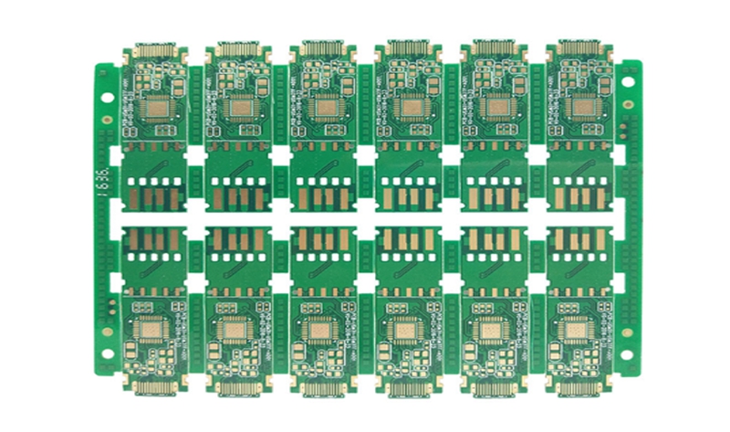
Learn how rigid PCBs compare to flexible PCBs, when to use one type better than another, and understand some of the manufacturing steps associated with these PCB types.
When using the term "PCB", many people think of rigid PCBs (printed circuit boards). However, the term PCB can refer to a rigid PCB or a Flexible PCB. Flexible PCBs are often called flexible circuits, but they are also known by other names, including flexible boards, flexible circuit boards, flexible printed circuit boards, and more formally flexible electronic devices. Flexible circuits have gained tremendous popularity recently because they can be shaped, bent, twisted, and folded into infinite configurations. However, in the end, rigid PCBs and flexible PCBs serve the same ultimate function in the most basic sense, connecting various electrical and mechanical components together.
Rigid PCBs
Rigid PCBs typically cost less than flexible circuits. Usually because when considering the total cost of ownership, some applications may be cheaper than using a rigid PCB when using a flexible PCB. To truly understand total cost of ownership, the first thing to understand is that flexible circuits can eliminate the need for components such as connectors, wiring harnesses, and other circuit boards. By removing these components from the design, material costs, labor and assembly costs, and scrap costs are reduced.
Many electronic devices (laptops and desktop computers, audio keyboards, solid-state drives (SSDs), flat-screen TVs and monitors, children's toys, and various electronic devices) use rigid PCBs instead of flexible PCBs. However, flexible circuits can be found in ultra-compact and / or high-performance devices, including GPS units, tablets, smartphones, cameras, and wearables. More complex circuits are not the only reason to use flex; low-tech applications (such as LED lights under counters, see the figure below) may use flexible circuit technology, which in some cases will make installation easier.
Some similarities and differences between Rigid PCB and flexible circuits. When designing a rigid PCB, certain design rules must be followed, including minimum hole size, minimum space and trace width, minimum distance to board edges, copper and overall design thickness. In addition, many manufacturing process steps are shared between rigid and flexible PCBs. These process steps include drilling and plating of holes and through holes, optical imaging and development, etching of copper traces, pads, contours and planes, and heating (baking) of circuit boards to remove moisture from the PCB. At this point in the manufacturing process, the rigid PCB leads to the solder mask and the flexible circuit enters the overlay. After completing the overlay lamination process, use drilling, wiring, or laser cutting to make any component and / or feature opening. Etching cannot be used.
Although both rigid and flexible printed circuit boards fundamentally serve the same purpose-connecting various electrical and mechanical components together, these two technologies have a place in life. Although many of the same design rules are used with rigid and flexible PCBs, flexible PCBs require some additional rules due to their extra manufacturing process steps. Although rigid PCBs appear to be cheaper (at least at the initial stage), the total cost of ownership of the design should be considered before announcing that flexible circuits are too expensive.
Finally, it is important to be careful not to be able to make flexible PCBs in all board rooms. Before starting a flexible circuit design, you should interview multiple boards and discuss flexible PCB construction options and associated costs. The above is the information about rigid and flexible PCB introduced by Flexible Board Manufacturer.

没有评论:
发表评论