2020年3月10日星期二

Which of the Rigid and Flexible PCB is Right for You?

Learn how rigid PCBs compare to flexible PCBs, when to use one type better than another, and understand some of the manufacturing steps associated with these PCB types.

When using the term "PCB", many people think of rigid PCBs (printed circuit boards). However, the term PCB can refer to a rigid PCB or a Flexible PCB. Flexible PCBs are often called flexible circuits, but they are also known by other names, including flexible boards, flexible circuit boards, flexible printed circuit boards, and more formally flexible electronic devices. Flexible circuits have gained tremendous popularity recently because they can be shaped, bent, twisted, and folded into infinite configurations. However, in the end, rigid PCBs and flexible PCBs serve the same ultimate function in the most basic sense, connecting various electrical and mechanical components together.
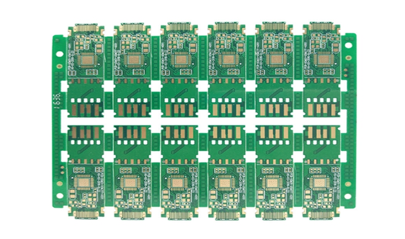
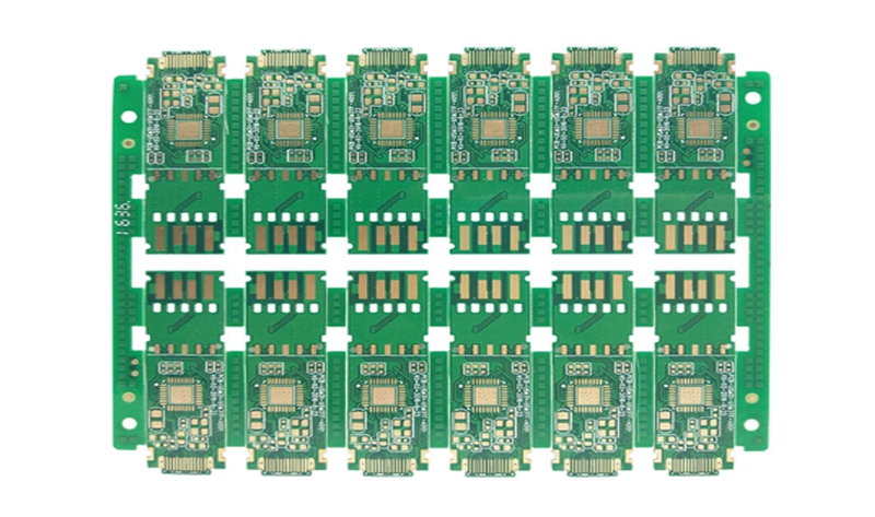
 Rigid PCBs

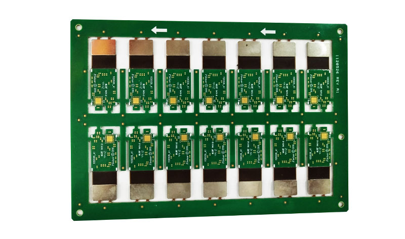
Rigid PCBs

Rigid PCBs typically cost less than flexible circuits. Usually because when considering the total cost of ownership, some applications may be cheaper than using a rigid PCB when using a flexible PCB. To truly understand total cost of ownership, the first thing to understand is that flexible circuits can eliminate the need for components such as connectors, wiring harnesses, and other circuit boards. By removing these components from the design, material costs, labor and assembly costs, and scrap costs are reduced.

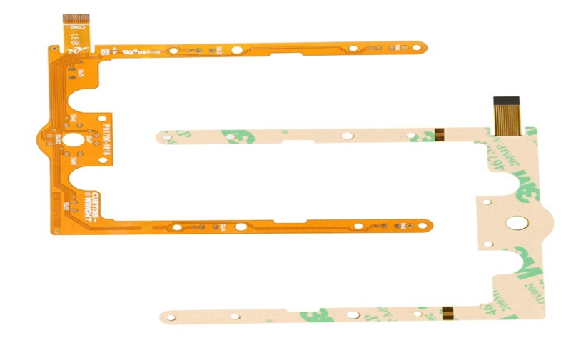
Many electronic devices (laptops and desktop computers, audio keyboards, solid-state drives (SSDs), flat-screen TVs and monitors, children's toys, and various electronic devices) use rigid PCBs instead of flexible PCBs. However, flexible circuits can be found in ultra-compact and / or high-performance devices, including GPS units, tablets, smartphones, cameras, and wearables. More complex circuits are not the only reason to use flex; low-tech applications (such as LED lights under counters, see the figure below) may use flexible circuit technology, which in some cases will make installation easier.

Some similarities and differences between Rigid PCB and flexible circuits. When designing a rigid PCB, certain design rules must be followed, including minimum hole size, minimum space and trace width, minimum distance to board edges, copper and overall design thickness. In addition, many manufacturing process steps are shared between rigid and flexible PCBs. These process steps include drilling and plating of holes and through holes, optical imaging and development, etching of copper traces, pads, contours and planes, and heating (baking) of circuit boards to remove moisture from the PCB. At this point in the manufacturing process, the rigid PCB leads to the solder mask and the flexible circuit enters the overlay. After completing the overlay lamination process, use drilling, wiring, or laser cutting to make any component and / or feature opening. Etching cannot be used.

Although both rigid and flexible printed circuit boards fundamentally serve the same purpose-connecting various electrical and mechanical components together, these two technologies have a place in life. Although many of the same design rules are used with rigid and flexible PCBs, flexible PCBs require some additional rules due to their extra manufacturing process steps. Although rigid PCBs appear to be cheaper (at least at the initial stage), the total cost of ownership of the design should be considered before announcing that flexible circuits are too expensive.

Finally, it is important to be careful not to be able to make flexible PCBs in all board rooms. Before starting a flexible circuit design, you should interview multiple boards and discuss flexible PCB construction options and associated costs. The above is the information about rigid and flexible PCB introduced by Flexible Board Manufacturer.

2020年3月4日星期三

Development Status Of Rigid Flexible PCB Technology

There are many benefits of hard and soft boards that many designers did not know before because their designs do not have to use this technology. However, more and more designers are now under pressure to build increasingly dense electronic devices. Even more troublesome is the continuous reduction in manufacturing costs and manufacturing time. In fact, this is really not a new technical issue.

The combination of soft board and hard board is likely to become a trap for novices on the road to the development of new technologies. Therefore, it is wise to understand how to make flexible circuits and hard and soft boards. In this way, we can easily find the hidden dangers in the design and prevent them from happening. Now let us know what basic materials are needed to make these boards. The following is a detailed introduction of Flexible Board manufacturer.

Rigid Flex PCB Board Design

Rigid Flex PCB Board Design

1. Substrate and protective film
First, we consider ordinary Rigid PCB, whose substrates are usually fiberglass and epoxy. In fact, these materials are a kind of fiber, although we call it "rigid", if you take a single layer, you can feel its elasticity. This layer can be made more rigid due to the cured epoxy resin. Because it is not flexible enough, it cannot be applied to some products. However, it is suitable for many electronic products that are simply assembled and will not continue to move.
In more applications, we need a flexible plastic film that is more flexible than ever. Epoxy. Our most common material is polyimide, which is very soft and strong, and we cannot easily tear or stretch it. In addition, it has incredible thermal stability and can easily withstand temperature changes during the reflow process during processing. It can hardly find its expansion and contraction during temperature fluctuations.
Polyester (PET) is another commonly used flexible circuit material, which has lower heat resistance and temperature distortion than PI film than polyimide (PI) film alone. This material is commonly used in low-cost electronic devices, where the printed wire is wrapped in a soft film. Because PET cannot withstand high temperatures, let alone soldering, flexible circuit boards are usually produced by cold pressing. I remember that the display part of this clock radio uses this flexible connection circuit, so this radio usually doesn't work properly. The root cause is this poor quality connector. Therefore, we recommend that PI films are still used for soft and rigid bonding boards. Other materials can also be used but are not often used.

2. Conductor
Printed wires are used for these money-saving electronics, usually carbon film or silver-based inks, but copper wires are still a popular choice. Depending on the application, we have to choose different forms of copper foil. If you are simply replacing wires and connectors to reduce manufacturing time and costs, then electrolytic copper foil for the right circuit board is the best choice. Electrolytic copper foil is also used to increase the current carrying capacity by increasing the weight of copper, so as to obtain a achievable copper skin width, such as a planar inductor.

3. Adhesive
Usually, we need an adhesive to bond copper foil and PI film. This adhesive was developed specifically for flexible circuit boards. "Adhesive-free" laminates are gaining popularity with copper on PI films due to the introduction of new processing technologies such as direct coating and deposition. When it is necessary to add protective beads on soft and hard joints, we will use silicone, hot melt adhesive or epoxy. This will increase the mechanical strength of the soft and hard joints, ensuring that stress fatigue or tearing does not occur during repeated use.

It is important to understand the materials used on a flexible circuit board or Rigid Flex PCB Board Design. We can also let manufacturers choose materials freely according to the application, but this will bring hidden dangers to the failure of the final product.

2020年1月27日星期一

Related Information About Flexible PCB Boards

Flexible PCB, its Chinese meaning is flexible printed circuit board, referred to as flexible board. It is made of conductive circuit patterns by using optical imaging pattern transfer and etching process methods on a flexible substrate surface. The inner and outer layers of the double-sided and multi-layer circuit boards are electrically connected through metallized holes. The surface of the circuit pattern is protected and insulated by PI and adhesive layer. It is mainly divided into single panel, hollow board, double panel, Multilayer Flexible PCB, and rigid-flex board.

Multilayer Flexible PCB

Multilayer Flexible PCB

There are 6 types of flexible PCB boards:
A. Single panel: There is a line on only one side.
B. Double panel: There are lines on both sides.
C. Hollow plate: also known as window plate (finger window).
D. Layered board: two sides of the line (separate).
E. Multi-layer boards: more than two layers of lines.
F. Flexible and rigid board: A product combining flexible and rigid boards.

The flexible board industry first emerged in Japan, dating back to about 2002. The flexible board industry outside Japan started to sprout in 2003, expanded rapidly in 2005, and declined in 2006. The flexible board industry bottomed out in 2007, and began to recover in 2008.

In 2005, the soft board industry had low thresholds and high profits, attracting a large number of enterprises to enter. In 2006, competition became increasingly fierce, and the phenomenon of oversupply was very serious. Many enterprises had to drop prices again and again to survive, or even lose money. At the same time, downstream customers of the flexible board industry, such as large EMS manufacturers, have added a flexible board department and no longer outsourced the flexible board business, which has made the flexible board industry worse.

Since the beginning of 2008, the global economy has seen a downward trend. Rising oil prices, the subprime mortgage crisis, and food prices have skyrocketed. The global economy has entered a downward path, especially in emerging countries. The decline in demand for FPCs comes from consumer electronics. When the economy is in a downward path, the first to be hit is the demand for these non-rigid consumer electronics products: including mobile phones, notebook computers, flat-screen TVs, LCD monitors, digital cameras, DV and other products.

The following Flexible Board Manufacturer introduces the characteristics of flexible circuit boards:⒈ Short: short assembly time, all lines are configured, eliminating the need for redundant wiring connections:
⒉ Small: Smaller than PCB (hard board), which can effectively reduce the volume of the product and increase the convenience of carrying;
3.Light: Lighter weight than PCB (hard board), which can reduce the weight of the final product;
4. Thin: The thickness is thinner than PCB (hard board), which can improve the softness and strengthen the assembly of the third space in the limited space.

A flexible printed circuit board is a printed circuit made of a flexible insulating substrate. It has many advantages that a rigid printed circuit board does not have:
1. It can be bent, rolled and folded freely, can be arbitrarily arranged according to the requirements of space layout, and can be moved and retracted in three dimensions, so as to achieve the integration of component assembly and wire connection;
2. The use of flexible PCB boards can greatly reduce the volume and weight of electronic products, and is suitable for the development of electronic products in the direction of high density, miniaturization and high reliability. Therefore, flexible PCB boards have been widely used in aerospace, military, mobile communications, laptop computers, computer peripherals, PDAs, digital cameras and other fields or products;
3. Flexible PCB board also has the advantages of good heat dissipation and solderability, easy assembly, and low comprehensive cost. The combination of soft and hard design also makes up for the slight insufficiency of flexible substrates in component carrying capacity.

The above is the information about the flexible PCB board introduced by the PCB Board Factory. Hope to help you.

2020年1月21日星期二

Use Flexible Rigid PCB To Produce More Reliable Products

Expensive and complex discrete interconnect cables can reduce design reliability, increase design cost and overall design size. Fortunately, there is an alternative to flex and Rigid Flex PCB Board. Flexible PCB provide a cost-effective and convenient solution for your design interconnect requirements, with the added benefits of PCB repeatability and reliability. Discrete interconnects have inherently different conductor orientations, while flexible PCB keep all conductors in a particular direction that is fixed to each other. The consistency of this combination allows accurate modeling of flexible PCB traces and more predictable designs. In addition, the Flexible PCB Circuit Board can include gold finger contacts, allowing the edge of the flexible PCB to be used as a convex portion of the connector and can accommodate high density designs. Because this flexible PCB can be used to replace most traditional discrete interconnect solutions, while still allowing a highly modular design.

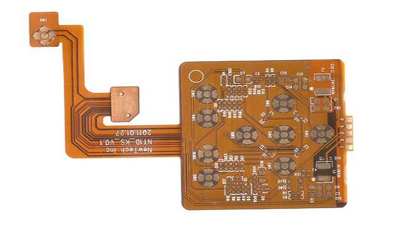
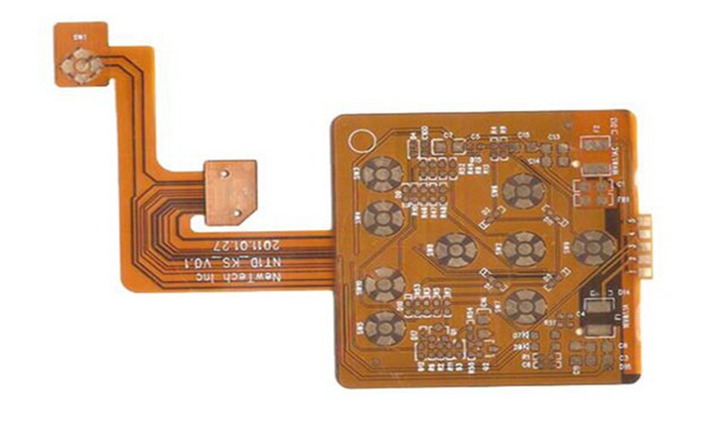
Flexible PCB Circuit Board

Flexible PCB Circuit Board

In addition to providing an effective way to design and produce interconnect solutions, flexible PCB can also house components and form the basis of the entire solution. The use of flexible PCB instead of traditional PCB allows for smaller and less traditional PCB designs that can be installed in a housing or they would not be able to accommodate traditional PCB. Instead of mounting the components on a rigid PCB, you can mount them on a flexible solution and they will conform to the contoured housing. In addition, parts of the flexible PCB can be reinforced with a reinforcing substrate to increase reliability. Finally, flexible PCB help achieve the slightest solution, because flexible PCB have significantly lower unit weight than traditional PCB. Examples of applications typically based on flexible PCB solutions include wearables, digital cameras, medical devices, and other small consumer electronics devices. Flexible PCB also have the advantage of inherent resistance to vibration. They are often used in automotive equipment because of their inherent resistance to vibrations and they are also very suitable for electronic equipment with mechanical parts. Therefore, they are widely used in printers, hard disks and keyboards.

Before sending the design for manufacturing, consider that the flexible board is flexible during the design process and that the design board has the highest density on the production board when nested. If bending can be used to achieve a specific size, bend in the installation, not in the initial design. Finally, using stiffeners with flexible PCB may be more cost-effective than flexible rigid designs. When you need fewer layers in your design, it may be more cost-effective to use a flexible PCB and add stiffeners to key parts of the board. Only consider flexible rigid solutions when your design has very large number of layers.

Finally, filling a flexible PCB is very similar to filling a rigid PCB. When performing flexible PCB assembly, consider the following tips:

In summary, flexible and flexible rigid PCB can greatly reduce the cost and complexity of your next product manufacturing process. Flexible PCB are a great alternative to traditional discrete wiring solutions, providing PCB repeatability and reliability in a flexible form factor. In addition, flexible rigid PCB provide the opportunity to create highly complex 3D designs while maintaining low assembly costs, high levels of repeatability and reliability. In short, flexible PCB will allow you to deal with designs that are too expensive, too complex or impossible to manufacture. Take your design to the next level with flexible or flexible rigid PCB.

2020年1月15日星期三

The Difference Between A Flexible Circuit Board And A Rigid Circuit Board

Printed circuit boards can be divided into rigid printed boards and flexible printed boards according to the materials made. Rigid printed boards include phenolic paper laminates, epoxy paper laminates, polyester glass felt laminates, and epoxy glass cloth laminates. Flexible printed circuit board is also called flexible printed circuit board or FPC. Flexible circuit board is a kind of printed circuit board with high reliability and high flexibility, which is made of polyimide or polyester film as the base material. Circuit board. This kind of circuit board has good heat dissipation, which can be bent, folded and rolled, and can be moved and retracted freely in three-dimensional space. FPC can be used to reduce the size, realize weight reduction, miniaturization, and thinness, thereby achieving integration of component devices and wire connections. FPC is widely used in electronic computer, communications, aerospace and home appliances industries.

So what does flexible circuit board and rigid circuit board mean? What is the difference? The Flexible PCB Circuit Board Supplier will tell you below.

Flexible circuit board product features:
The product is small in size and light in weight, which greatly reduces the size of the device, and is suitable for the development of electronic products toward high density, miniaturization, light weight, thinness, and high reliability.
It has high flexibility, can be freely bent, rolled, twisted, folded, and three-dimensional wiring. Arbitrarily arranged according to the requirements of space layout, change the shape, and move and expand freely in three-dimensional space to achieve assembly and wire connection Integration.
Has excellent electrical properties, high temperature resistance, flame resistance. It has stable chemical changes, good stability and high reliability.
It has higher assembly reliability, provides convenience for circuit design, can greatly reduce assembly workload, and easily guarantees the performance of the circuit, reducing the cost of the whole machine. The strength is increased by using reinforcing materials to obtain additional mechanical stability.

Rigid PCB Features:
High density. For more than 100 years, the high density of printed boards has evolved with the increase in integrated circuit integration and advances in mounting technology.
High reliability. Through a series of inspections, tests and aging tests, the PCB can be guaranteed to work reliably for a long period of time (usually 20 years).
Designability. For various performance requirements of PCB (electrical, physical, chemical, mechanical, etc.), printed board design can be realized through design standardization and standardization, with short time and high efficiency.
Productivity. With modern management, standardization, scale (quantity), automation and other production can be carried out to ensure consistent product quality.
Testability. Established relatively complete test methods, test standards, various test equipment and instruments, etc. to detect and identify the qualification and service life of PCB products.

Flexible PCB Circuit Board

Flexible PCB Circuit Board

The difference between Flexible PCB Circuit Board and rigid circuit board:

The rigid circuit board and the flexible circuit board both had similarities and differences at the same time.
1. Current carrying capacity of wires: Compared with rigid circuit boards, the heat dissipation performance of flexible circuit boards is relatively poor, so sufficient wire width must be provided. Because the heat dissipation of the flexible circuit board is considered, extra width or spacing needs to be given to the wires.
2. Shape. Under normal circumstances, rectangles are selected, which can save the substrate very well, and there should be enough free margins near the edges. A sharp inner corner may cause tearing of the board. Therefore, the smaller wire width and spacing should be minimized, and the transition must be as smooth as possible. Sharp corners will naturally concentrate stress and cause lead failure.
3. Flexibility: Of course, the flexibility of rigid circuit boards is not comparable to that of flexible circuit boards. For a large number of bending cycles, flexible circuit boards have better performance.

The above is the difference between a rigid circuit board and a flexible circuit board.

2020年1月10日星期五

Different Structure Of PCB Circuit Board

PCB is made by processing a variety of complex process wires and different types of components. The printed circuit board structure is also very complicated, including single layer, double layer and even multiple layers. The production method will be different at different levels. There are many types of circuit boards developed so far. Printed circuit boards can also be classified according to their hardness. There are rigid boards (rigid boards), flexible boards (FPC), and rigid-flex circuit boards. Usually more rigid boards are used. Generally, circuit boards are divided into layers according to the number and thickness of conductive copper foils. They can be divided into single-layer boards, double-layer boards, multilayer boards and double-sided boards. Their structures are also different. Flexible PCB Circuit Board Supplier will introduce their different properties.

Single-layer board structure: This is the simplest structure of the flexible board, usually with a base material + transparent glue + copper foil purchased raw materials, and protective film + transparent glue is another purchased raw material; first, copper The foil needs to be processed by etching and other processes to obtain the required circuit. The protective film is drilled to expose the corresponding pads. After cleaning, the two are combined by rolling, and then the exposed pads are plated with gold or The tin is protected, so that the large board is ready, and then it needs to be stamped into a small circuit board of the corresponding shape.

Double-layer board structure: When the circuit is too complicated, single-layer board cannot be wired, or copper foil is needed for ground shielding, you need to choose double-layer board or multilayer board.

Multilayer Flexible PCB

Multilayer Flexible PCB

Multilayer board structure: The most typical difference between a multilayer board and a single-layer board is the addition of a via structure to connect the various layers of copper foil. The first processing process for general substrate + transparent glue + copper foil is to make vias; First, drilling holes in the substrate and copper foil, and then plating with a certain thickness of copper after cleaning, so that the via holes are completed. The subsequent manufacturing process is almost the same as that of the single-layer board.

Double-panel structure: There are pads on both sides of the double-panel, which is mainly used for connection with other circuit boards. Although it has a similar structure to a single-layer board, the manufacturing process is very different. Its raw materials are copper foil, protective film + transparent glue. First, you need to drill holes in the protective film according to the requirements of the pad location, and then paste the copper foil. Then etch out the pads and leads before attaching another drilled protective film.

Although these types of structures of flexible circuit boards are of different types, such as Multilayer Flexible PCB, many manufacturing processes have similarities, but different processes have been added in some basic places to correspond to different fields.

The above is the different structure of PCB circuit board introduced by Rigid PCB Manufacturer. I hope it can help everyone.

2020年1月6日星期一

PCB Circuit Board Cooling Tips

The heat generated during the operation of electronic equipment causes the internal temperature of the equipment to rise rapidly. If the heat is not dissipated in time, the equipment will continue to heat up, the device will fail due to overheating, and the reliability of the electronic equipment will decline. Therefore, it is important to dissipate heat from the circuit board. So what should be done specifically? The Flexible PCB Circuit Board Supplier will tell you below.

1.High heat generating device plus radiator and heat conduction plate
When there are a few devices in the PCB with a large amount of heat (less than 3), a heat sink or a heat pipe can be added to the heating device. When the temperature cannot be lowered, a heat sink with a fan can be used to enhance heat dissipation. effect. When there are a large number of heating devices (more than 3), a large heat shield (board) can be used. It is a dedicated heat sink customized according to the position and height of the heating device on the PCB board or a large flat heat sink. Cut out different component height positions. The heat sink is buckled on the surface of the component as a whole, and contacts each component to dissipate heat. However, the heat dissipation effect is not good due to the poor consistency of the components during assembly and welding. Generally, a soft thermal phase change thermal pad is added on the component surface to improve the heat dissipation effect.

2. Heat dissipation through the PCB board itself
At present, the widely used PCB boards are copper-clad / epoxy glass cloth substrate or phenolic resin glass cloth substrate, and there are a few paper-based copper-clad boards used. Although these substrates have excellent electrical properties and processing properties, they have poor heat dissipation properties. As a heat dissipation method for highly heat-generating components, it is almost impossible to rely on the PCB resin to conduct heat, but to dissipate heat from the surface of the components to the surrounding air. However, as electronic products have entered the era of component miniaturization, high-density mounting, and high-heat assembly, such as Rigid Flex PCB Design, it is not enough to dissipate heat only by the surface of the component with a very small surface area. At the same time, due to the large use of surface mount components such as QFP and BGA, the heat generated by the components is transferred to the PCB board. Therefore, the best way to solve the heat dissipation is to improve the heat dissipation capability of the PCB itself that is in direct contact with the heating element.

Rigid PCB

Rigid PCB 

3.Use reasonable wiring design to achieve heat dissipation
Due to the poor thermal conductivity of the resin in the plate, and the copper foil lines and holes are good conductors of heat, increasing the copper foil residual rate and increasing the heat conduction holes are the main means of heat dissipation. To evaluate the heat dissipation capability of a PCB, it is necessary to calculate the equivalent thermal conductivity of a composite material composed of various materials with different thermal coefficients-an insulating substrate for a PCB.

4. For equipment using free convection air cooling, it is best to arrange integrated circuits (or other devices) in a vertical or horizontal manner.

5. The devices on the same printed board should be arranged as much as possible according to the amount of heat generated and the degree of heat dissipation. Devices with low heat generation or poor heat resistance (such as small signal transistors, small-scale integrated circuits, electrolytic capacitors, etc.) should be placed. At the top of the cooling airflow (at the entrance), devices with high heat generation or heat resistance (such as power transistors, large-scale integrated circuits, etc.) are placed at the most downstream of the cooling airflow.

6. In the horizontal direction, high-power devices should be arranged as close to the edge of the printed board as possible to shorten the heat transfer path; in the vertical direction, high-power devices should be arranged as close to the top of the printed board as possible to reduce the temperature of these devices on other devices during operation.

7. The temperature-sensitive devices are best placed in the lowest temperature area (such as the bottom of the device). Do not place them directly above the heating device. Multiple devices are preferably staggered on the horizontal plane.

The above is the heat dissipation technique of PCB circuit board introduced by Rigid PCB Manufacturer. I hope it can help everyone.